


Car & Truck Wiring Diagrams, EMS Pinouts & Sensor Data: A Technician’s Complete Guide (2026)
 May 31,2026
  By Fixomotive
Car & Truck Wiring Diagrams, EMS Pinouts & Sensor Data
How to read a wiring diagram, decode an EMS/ECM pinout, and use real sensor details to fix Indian cars and commercial vehicles in minutes — not hours.
Try Fixomotive Repair free →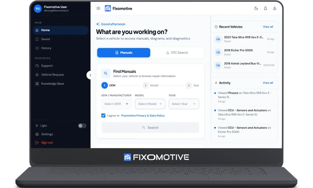
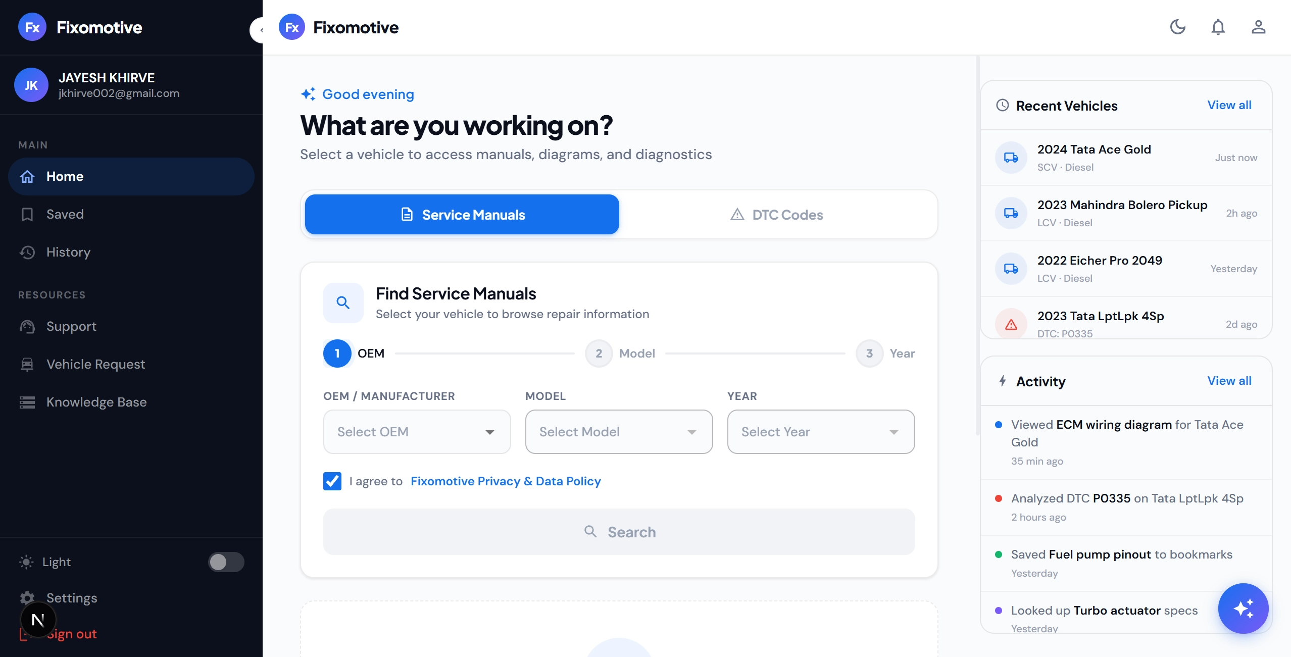
A wiring diagram shows how every circuit and component is connected; an EMS pinout maps each ECU pin to its wire colour, signal and reference voltage; and sensor details give you the specs, location and failure patterns of each component. Used together, they turn electrical guesswork into a precise, repeatable diagnosis — which is exactly what Fixomotive Repair puts in one place.
Ask any experienced auto electrician where repairs actually go wrong, and the answer is rarely the engine — it's the information. A blurry photocopied car wiring diagram. A truck wiring diagram that belongs to a different model year. A pinout for the wrong variant. A sensor swapped on a hunch that didn't fix the fault. On Indian commercial vehicles especially, where one P0087 can hide behind a chafed wire, a corroded connector or a genuinely failed sensor, the gap between a 30-minute fix and a two-day headache is simply having the right data the moment you need it.
Here's the chain that good diagnostics actually follows — and the three documents that power it:
01Wiring diagrams: from blurry PDFs to interactive circuits
A car or truck wiring diagram is the single most important document in electrical diagnosis. It tells you which wire carries power, which carries the signal, which is ground, and exactly where each one runs between the ECU, the sensor, the fuse box and every connector in between. The problem isn't that wiring diagrams don't exist — it's that the ones most technicians can find are static PDFs, often the wrong variant, often unreadable on a phone.
An interactive wiring diagram solves this. Instead of a flat image, the circuit becomes clickable and zoomable. You can trace a signal path from the sensor back to the exact ECU pin, tap any component to open its details, and simulate signal flow to see how the circuit should behave before you start probing. When the diagram is colour-coded the way the harness actually is, you stop second-guessing which of three brown wires you're looking at.
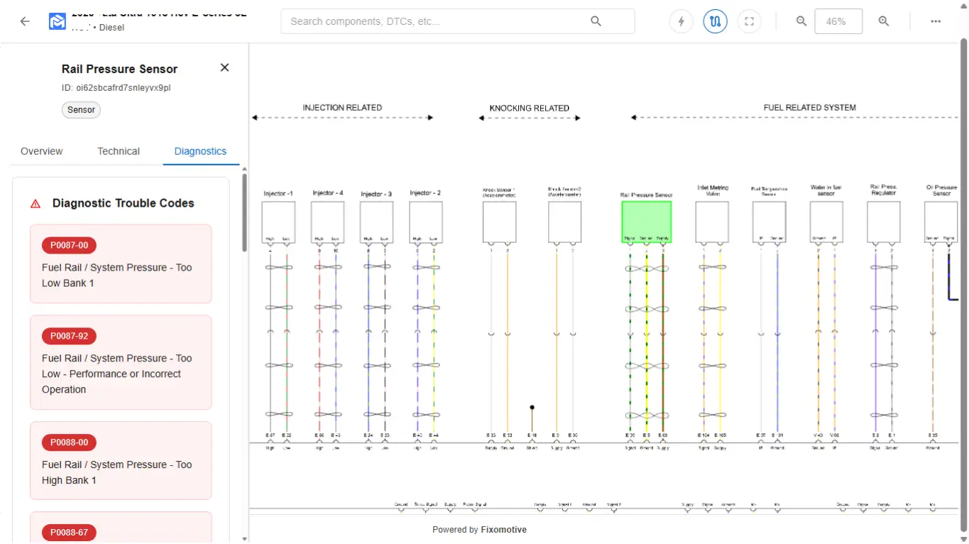
What a good wiring diagram should let you do
- Trace a circuit end-to-end, from sensor to connector to ECU pin
- See real wire colours and connector positions, not a generic schematic
- Jump directly from a DTC to the circuit that triggered it
- Simulate signal flow to know the healthy baseline before testing
- Open it on a phone or tablet, right next to the vehicle
02EMS / ECM / ECU pinouts: the fastest path to a fault
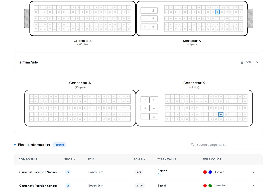
Once the wiring diagram tells you which circuit, an EMS pinout tells you exactly where to test. EMS stands for Engine Management System; the pinout is the map of the ECU connector — every pin numbered, with its wire colour, the component it serves, and the reference voltage you should measure there. (You'll also see it called an ECM pinout or ECU pinout; same idea, different label.)
This is what turns a multimeter from a guessing tool into a confirmation tool. If pin 42 should read a 5 V reference and you're measuring 0 V, you instantly know whether the fault is the sensor, the wiring, or the ECU — no harness teardown required.
| Pin | Function | Wire | Ref. |
|---|---|---|---|
| A-12 | Rail pressure signal | Grn/Wht | 0.5–4.5 V |
| A-42 | 5 V sensor supply | Red | 5.0 V |
| A-18 | Sensor ground | Black | < 0.1 V |
03Sensor & component details: know it before you replace it
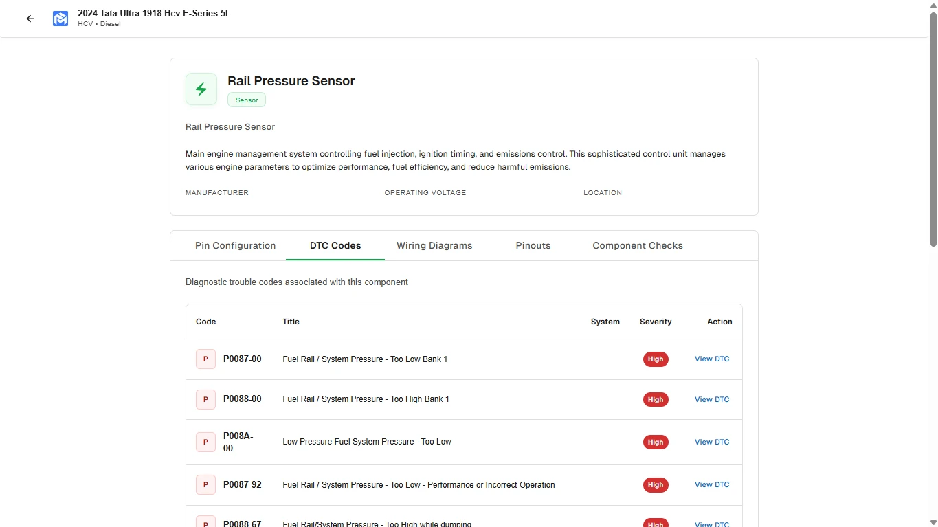
The most expensive habit in any workshop is replacing a part on a guess. Detailed sensor and component data closes that gap. For each component you want its location on the vehicle, its electrical and operating specifications, the parameters it should read under normal conditions, the correct replacement procedure, and — critically — the failure patterns that point to it.
Take a rail pressure sensor throwing P0087 (low rail pressure) or P0088 (high rail pressure). The component page should tell you where the sensor sits, what voltage it outputs across the pressure range, which DTCs it's linked to, and how its wiring runs back to the ECU — so you can decide between cleaning a connector, repairing a wire, or actually replacing the sensor.
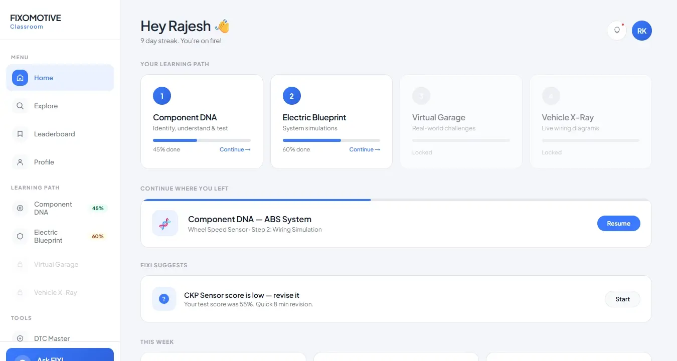
04Tying it together: DTC intelligence + Fixomotive AI
Indian commercial vehicles use a mix of standard J1939 codes (SPN/FMI), manufacturer-specific codes, and BS6 emission codes covering NOx, DPF, SCR and DEF faults. On its own, a code is just a number. The value comes from instantly linking it to probable causes, affected components, the right wiring diagram and the test steps — and being able to ask follow-up questions in plain language.
That's the job of Fixomotive AI, the platform's internal AI assistant. Trained on real Indian workshop data rather than generic web content, it answers in under 30 seconds, in your language, specific to your vehicle's make, model and year. Ask it what a code means on a particular truck and it doesn't give you a forum guess — it gives you the cause tree, the components involved, and a path straight into the wiring and pinout for that vehicle.
Ask in plain language. Get a repair-ready answer.
No generic AI fluff — context-aware guidance tied to the exact vehicle.
05Built for Indian commercial vehicles — in 11 languages
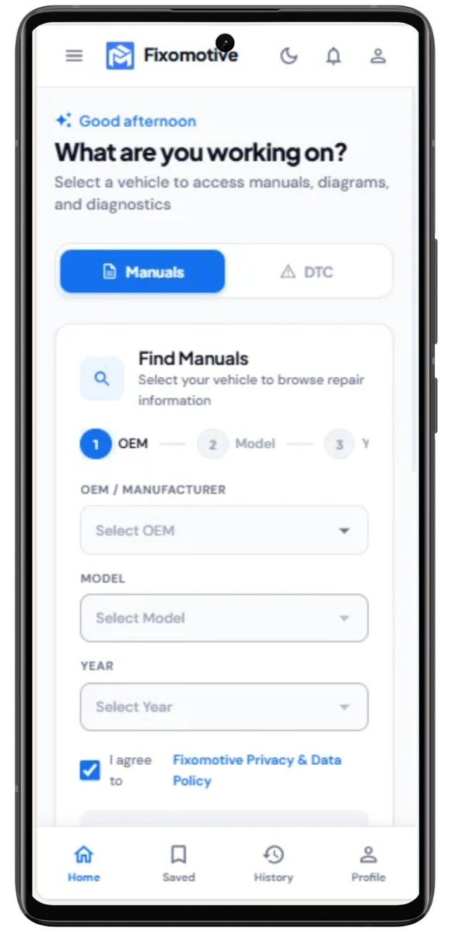
Most global diagnostic tools (ALLDATA, Mitchell1, Identifix, Bosch ESI[tronic]) carry thin India-specific content and ship in English only. Fixomotive Repair is built the other way around: deep coverage of India's major CV brands across BS4 and BS6, with new models added every week, and the entire platform — interface, AI answers and repair guidance — available in 11 Indian languages. Passenger-car coverage is launching in August 2026.
It also works with or without a diagnostic scanner — as a standalone knowledge platform on its own, or alongside scanners like Launch, Thinkcar and Denso if you already use one. No more switching between PDFs, YouTube, WhatsApp groups and scanner software for a single repair.
Stop digging. Start fixing.
Try Fixomotive Repair free — interactive wiring diagrams, EMS pinouts, sensor data and Fixomotive AI for India's commercial vehicles.
Start your free trialFrequently asked questions
What is an EMS pinout and why do technicians need it?
Are interactive wiring diagrams better than PDF service manuals?
Do I need a diagnostic scanner to read wiring diagrams and sensor data?
Which vehicles are covered for wiring diagrams and pinouts?
What sensor details does Fixomotive Repair provide?
Fixomotive Repair is an AI-powered troubleshooting platform for Indian commercial-vehicle technicians — wiring diagrams, DTC intelligence, component data and EMS/ECM pinouts in one app. Explore Fixomotive Repair →


